Friday, August 30, 2013

Mounting the beast

I got the motor pretty well set in place where I needed it now was time to level it off. I needed a flat spot on the motor to get it properly leveled. I used the lower intake manifold of the 350z as a place to rest my torpedo level for reference. I set a block of wood between where the k member goes under the engine for clearance as well as clearance of the steering rack. After a few attempts to get the engine to sit level freely I realized I was going to need something to temporarily hold the engine level and in place to weld up the motor mount brackets needed. I realized I had just the thing to do the trick. You might laugh but it did the trick. We had a whole bag of long zip ties normally used commercially for holding HVAC duct work to diffusers in the ceiling. It ended up being perfect for what I used them for, a temporary place holder for the engine. So I centered  the motor in the engine bay, leveled it off from front to back and side to side. I zip tied it in place in conjunction with using the engine hoist to keep it supported.


Motor now set, I was surprised to see the motor mount bracket mounting point on the block was in line with the k member. This is a good sign because I won't have to make a custom k member and it means the motor is near center on the k member for weight distribution. I found that I could drill the holes for the mount and have it offset enough to clear the steering rack like so:


It doesn't look like the 350z manifolds will clear my mount bracket so they will be removed for now. Hopefully the Nismo Frontier headers will clear if not ill just fabricate ones that will.

So now to make the first basic parts of the brackets, the mount plate to the engine and the mount plate to the motor mount itself. 

The plates to the engine are simple trace and cut out, then test fit to engine.


Then looking at the mount I found that that plate can be a perfect circle. I got out my hole saws and found one roughly the size of the mount.


Cut out the plate:

Being that hole saws use a pilot bit to hold them in place, it drills a small hole dead center of the plate which works out perfect for my needs. The pilot hole was two small so I just drilled it out bigger to suit the mount.


Perfect fit except there is a alignment dowel as I call it that won't allow the plate to sit flat unless it is also drilled into the plate.


So I took a nut and bolt and held the mount plate in place on the stock 350z mount arms.


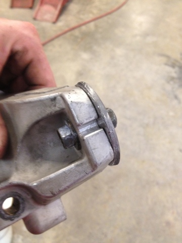
Found a drill bit about the same size as the hole needed to be drilled. Drilled it.


Result:

Test fitted:

Like a glove! With all my mount plates fabricated and ready to go its time to make the mount arms needed. I bolted the engine to mount bracket plates to the engine and then bolted the mount bracket plates to motor mount plates to the motor mounts. Using card board and tape I made templates for the arms needed. I then traced them on the metal and cut them out. Once cut out I tack welded them in place.

I noticed that my drivers side mount is slightly under the body of the Miata. I am all about ease of maintenance so I am going to position the passenger side mount in a little closer to the engine for clearance and ease of engine removal if I ever have to pull it back out.  

So I placed the passenger side mount in place all the while being careful not to obstruct the starter.  I then did the same thing I did for the drivers side mount bracket, made a template and tack welded the arms in place. I cut loose the zip ties and rechecked my torpedo level.


Still level!

Pulled the motor out. Pulled the brackets off. Welded them solid. Sand blasted them in preps for powder coating later.

Drivers side:

Passenger side:

I will be putting the car on my lift next and bolting the transmission to the engine in preparation for making the transmission mount. 


Thursday, August 22, 2013

Stuffing the engine in...

As I mentioned I am using a VQ30DET for this build. I actually have a few variants of the VQ series engines in my possession. I have a VQ30DE from a Maxima and a damaged VQ35DE from a G35x (350z engine). So with the various engines I am able to mix and match parts from the different engines to "Frankenstein" a VQ engine together to suit my needs. For fitment purposes I will be using the damaged VQ35. 

The VQ30DET uses motor mounts that are the same as a R32 Skyline. I have Nismo R32 mounts with 350z motor mount brackets I am hoping will work for my application. I also have a set of stock 350z manifolds to use as I am certain I will most likely have to do a rear mount turbo setup. 

After pulling the motor and reading various other Miata builds it became clear that I would have to convert my VQ to rear sump for clearance of the stock Miata K frame. Luckily there is a solution to this small problem. 

Nissan used the VQ series engine in the 2001-2004 Pathfinder which utilized a rear sump. So I bought the upper and lower oil pan off a Pathfinder and went to work.


I also ordered a new oil pick up tube, oil baffle, oil dip stick tube, oil dip stick and various gaskets new from Nissan. 

I popped the upper and lower oil pan off the VQ30DET. First thing I did was test fit the new Pathfinder oil pick up tube. 


Next thing I did was test fit the Pathfinder oil baffle. I found that the bolt holes needed to bolt down the oil baffle were missing on the VQ30DET torque plate (I think that's the name for it)


Thinking I was going to have to order a new plate from Nissan, I decided to pop open my damaged VQ35DE to see what it's plate looked like. I was surprised to find bolt holes where I needed them on its plate.


So I laid the oil baffle on it and found it lined up perfectly. 


Happy that I didn't have to purchase more parts I took everything and test fitted them on the VQ30DET. Everything went on without a hitch.


Then lastly I fitted the upper and lower oil pan, they too went on without a hitch. Only thing I will have to do is tap and plug the factory dip stick location on the VQ30DET and drill the block in the exact same location for the dip stick as the pathfinder block.


Now that I know everything fits the VQ30DET. I removed the upper and lower oil pan, as well as the motor mounts and brackets. I installed them on my damaged VQ35DE motor as well as the 350z headers and G35 transmission.


Ready for test fit!

Well first thing first I had to notch the subframe as you can see by this picture the oil pan is off center.


The oil cooler was also removed as it interfered with the steering rack. 

Transmission had to be removed as the engine could not be angled enough to clear the steering rack with the transmission attached.

The stock 350z manifolds were cut as they were too long and hit the fire wall. They will be replaced with shorter VQ40DE Nismo headers for a 05-13 Pathfinder/Frontier


I then found that the 350z motor mount brackets are not going to work for my needs. I will still use the Nismo Skyline motor mounts but the brackets I will have to custom make myself, no worries. After some measuring here is how the motor will sit:


The motor sits a little high and will surely have hood clearance issues. I plan to remedy this by elongating the stock Datsun Roadster hood scoop, which should give the roadster a more aggressive look.

The motor sitting at its lowest results in the oil pan sitting a inch or so past the bottom of the K member. This obviously won't work. Once the motor is mounted I will remove the upper oil pan and cut out a section of it reducing the length to be even or just barely past the K member and weld the pan back together. 


Friday, August 16, 2013

Engine removed, my what pretty eyes she has.

Removed the engine today in preparation for fitment of the VQ and cleaning of the engine bay.


Pretty easy to get out especially when I got to use the new lift we had installed in our shop. I highly recommend to any car guy that they get a lift if they get a chance makes life so much easier.

The chrome G-Class headlights came in. I was happy to find the front lens on these were glass unlike the plastic black housing ones I originally had. I like the glass because they are less likely to scratch and turn yellow over time. The chrome housing looks much better. 


Wednesday, August 7, 2013

Cooling and Lights

After mocking up the core support I had a realization and that was I could possibly use a brand new intercooler I had laying around from a previous aborted S14.5 project. So I grabbed it off the shelf and my hunch was correct, actually I was surprised how well it fit! So I welded a top  support and positioned it where I wanted it right behind the grill. 

I then started to tie the entire core support to the top fender supports I mocked up.

In order to finish off the front underbody I needed to finish off the sections where the headlights would be housed. I am not a fan of the stock old halogen type headlights that the Roadster initially uses. After searching the Internet for a suitable replacement with the desire of projectors and HIDs in mind, I came across these: 


Mercedes G class HID projector lamps. Yes they are DEPO headlights as I can't justify buying headlights that are more expensive than the entire car. I went with black housing as I intended the car to be black on black with the factory Roadster chrome trim highlights.

After some trimming of the inside of the fender, the underbody and headlight plate mount I had the headlight positioned and mounted where I wanted it.


As you can see I spray painted around the headlight black to get an idea of how it would look in black with the chrome trim and headlights. After looking at the car from every angle walking back and forth starring at the car. I quickly realized black housing headlights were a bad choice. So frustrated I shelved the black housing headlights and ordered the chrome housing that look like these:
I know this will be the better choice. I think the black just looked out of place and pulled away from the "era" and look of the car.


Saturday, August 3, 2013

Replacing what I cut out

Going with the whole idea of stretching the body of the Roadster to fit the Miata, I decided to duplicate the Roadster core support to fit the Miata. I did not want to hack up the original grill in attempts to elongate it mostly because I don't think it would look right. I purchased a 2000 grill as I was not a fan of the original 1600 grill. I used newer and thicker angled steel since this car will be driven without the original crash bar of the Miata. After squaring up and measuring multiple times here are the results. 


I still have some more to add to the core support like hood latch and headlight supports as well as bracing to run along where the fender meets the hood but overall I am extremely happy with the results on the fitment.

Here is a shot with the grill loosely bolted in place and the hood laying on top about where it should be. (hood is sitting high in the back as it is resting on the windshield wipers, it will lay more flat once it is cut to fit) Metal bent and formed to the Roadster body lines will be added to fill in the gaps.


Thursday, August 1, 2013

Lets get to cutting....

Ok so obviously to get started we need to remove the Miata front end. 


I'm not changing anything on the Miata in the center of the car. The doors will stay as they are. So what I need to do is make the Roadster fenders mate with the  Miata doors. So I am going to be combining Miata fenders with Roadster fenders. 

The Roadster fender test fit:


As you can see the core support of the Miata, as expected, will have to be cut for the Roadster fender to fit the Miata wheel well correctly. As you can also see the Roadster fender is more straight down at the bottom where as the Miata fender curves in. We will have to cut the Roadster fender right where the Miata fender starts to curve in.

So after removing the Miata core support and cutting to get the Roadster fender to sit back far enough, we can get a good idea of where we need to cut the fenders to mate to each other by laying the fenders over each other and using the wheel arches as reference. 

First I drew a rough line of the area we need to save on the Miata fender leaving more than enough room to trim as needed:

Cut it with a cut off wheel:


Then I overlaid the needed portion of the Miata fender on the Roadster fender using the wheel arch as reference:

Then I also cut the Roadster fender with a cut off wheel after I marked where I needed to cut making sure I leave enough metal for the fenders to overlap:


I then bolted the cut Miata fender to the Miata. As I did this I took the Roadster fender and overlaid it on the Miata fender. I positioned the Roadster fender where I wanted it on the car (again using the wheel arches as reference) I then laid the roadster hood on the Miata, centered it, used tape to temporarily hold it in place. Using the hood and wheel arches, I tack welded the Roadster portion of the fender in place while also using a level on the bottom lip of the fender to make sure everything was sitting straight. Once both fenders were positioned where I wanted them and overlaying each other I then used a cut of wheel and cut exactly where they met and stitch welded them together. The result was this:


(Passenger side shown)

Both sides tacked welded into position and leveled off. Double checked for symmetry and proper alignment:


Next is time for the core support mock up.